1734 Ib8 Wiring Diagram
3 view dimension drawings (3d format) catalog number. Nc field power is supplied from power bus.
This module has a maximum field power bus supply voltage of 300 v with maximum supply current of 10 a.
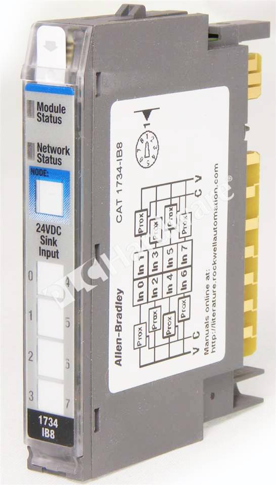
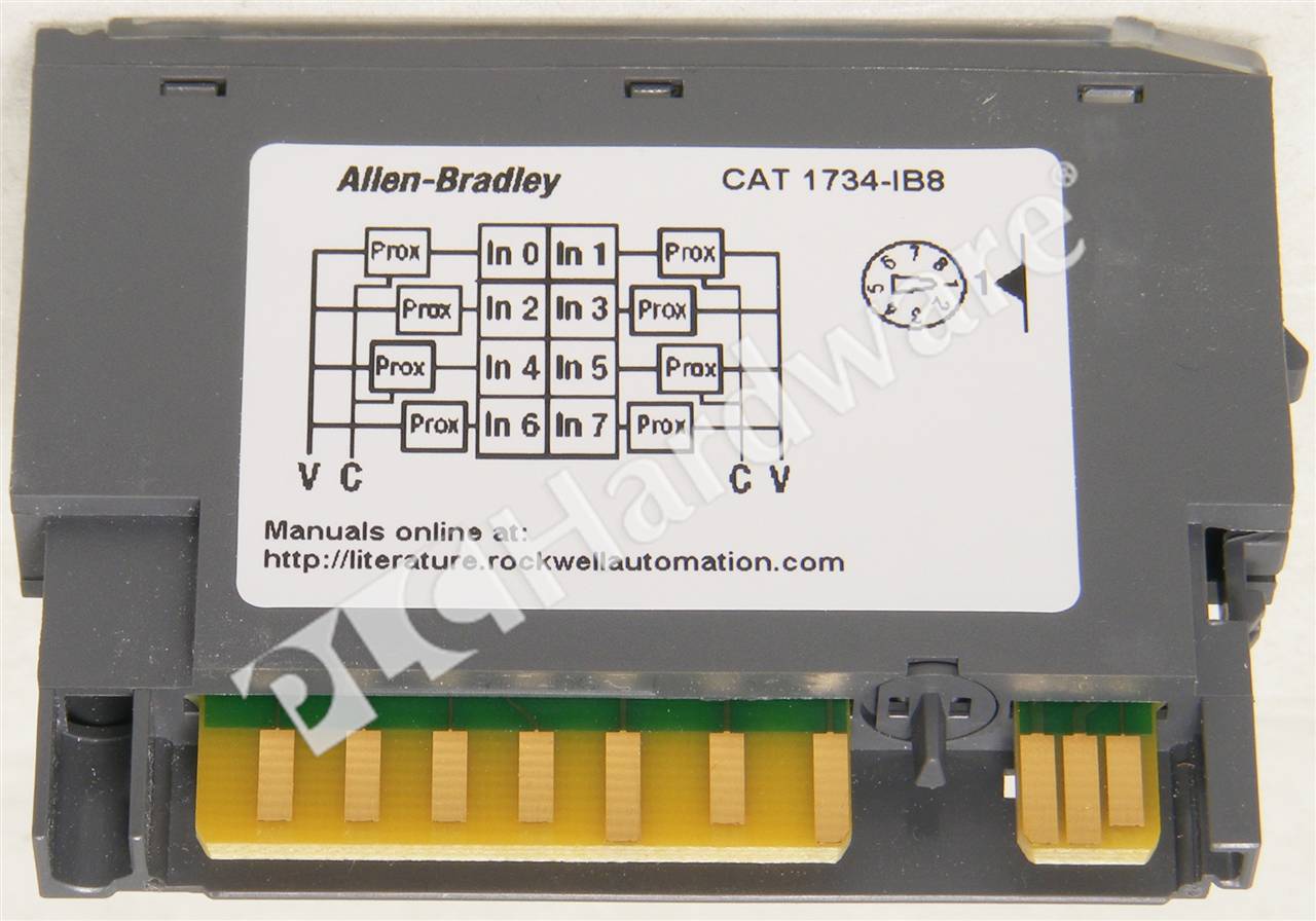
1734 ib8 wiring diagram. We carry the entire point i/o 1734 series. Wiring the sensor to point io. On 1734 ob8s wiring diagram.
The rtbs are part of the terminal base assembly. This list includes substantive updates only and is not intended to reflect all changes. Ow2 and ow4, series c).
Wiring base assemblies, miscellaneous cold junction wiring base assembly installation instructions, publication. The examples and diagrams in this manual are included solely for illustrative purposes. Comprehensive diagnostics and configurable features makes point i/o™ easy to apply.
Wiring+diagram+ie8c datasheet, cross reference, circuit and application notes in pdf format. 1734 ib8s wiring diagram from www.plchardware.com print the electrical wiring diagram off in addition to use highlighters to trace the routine. Ow2 and ow4 relay output module s ow2 modules with load powered by internal power bus.
In addition to this wiring, terminals 9 & 10 on the transmitter will be wired to the same 24v and common as my plc modules. They are not included with the i/o modules and must be ordered separately. Learn how to avoid the risks of unauthorized and counterfeit products.
On 1734 ow4 wiring diagram. Modules slide together for easy install and uninstall for easier maintenance. Because of the many variables and.
• 1734 specialty i/o modules. Each input is tied into the terminal of the base which can be selected to be spring clamp or a screw terminal. The examples and diagrams in this manual are included solely for illustrative faults at the door interlock switch, wiring terminals or safety controller will be detected the ib8s input module monitors two door channels and two lock.
Removable wiring system saves time and money during installation and troubleshooting. Modular design lets you independently select the i/o, termination style, and network interface. This assembly has twelve (12) spring clamp terminals.
Autocad® (dwg) drawing interchange format (dxf) adobe® pdf. • 1734 analog i/o modules. The examples and diagrams in this manual are included solely for illustrative faults at the door interlock switch, wiring terminals or safety controller will be detected the ib8s input module monitors two door channels and two lock.
This manual is a reference guide for the aentr, aentr, series b. The card features 8 distinct inputs. 1 trick that we 2 to print the same wiring plan off twice.
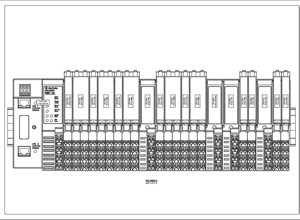
• 1734 network communication adapters. Description wiring base assembly consists of item 1) mounting base, mb and item 7) removable terminal the examples and diagrams in this manual are included. • 1734 digital i/o modules.
I'm not going to be using the analog loop. Afterward trying to remove, replace or fix the wiring in an automobile, having an accurate and detailed 1734 iv8 wiring diagram is vital to the. Catalog numbers ib2, ib4, ib8, series c.
The point family of i/o modules includes: Topic page summary of changes 1 environment and enclosure 3 north american hazardous location. When you employ your finger or stick to the circuit together with your eyes, it may be easy to mistrace the circuit.
Using a 1734IB8 to Count Flow Meter Pulses Allen Bradley
AllenBradley 1734OB4 17340B4 Output Module Series C / FW 3.022

Point IO 1734 Allen Bradley Input Sensor Hardware Installation Wiring Testing Programming Tutorial
20 Fresh 1734Ow4 Wiring Diagram
1734 Ib8s Wiring Diagram Wiring Diagram
PLC Hardware Allen Bradley 1734IB8S Series B, New Surplus Open
1734 Ib8S Wiring Diagram For Your Needs
Using a 1734IB8 to Count Flow Meter Pulses Allen Bradley

Allen Bradley 1734ib4 Wiring Diagram
PLC Hardware Allen Bradley 1734IB8 Series D, Used in a PLCH Packaging


